Overview & Context
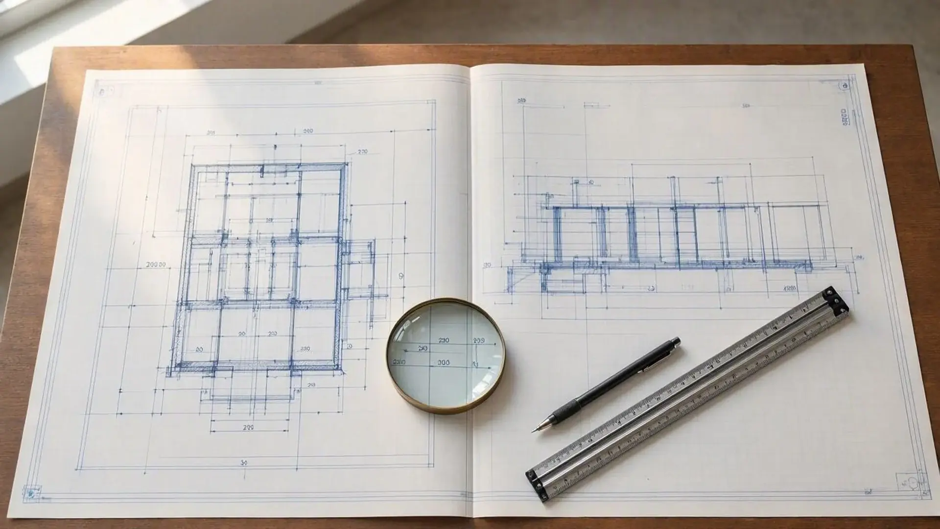
OverviewIf you have ever received a PDF of construction drawings and felt overwhelmed, you are not alone. Architects and drafters use a standardized visual shorthand that takes years to master. However, homeowners only need to understand four core concepts to review their project confidently.
In BC, all permit-ready drawings must follow a strict hierarchy. Understanding this order prevents costly miscommunication between you, your contractor, and municipal reviewers.
Step 1: Check the Title Block & Scale (Imperial vs Metric)
Phase 01Every professional drawing sheet includes a title block. This is your "metadata". It contains: - Project name, address, and drawing title - Scale (e.g., 1/4" = 1'-0", 1/8" = 1'-0", or 1:50, 1:100). Most BC construction drawings use imperial (feet and inches), but both imperial and metric are accepted for permit submissions. Always check which system is being used for your project. - Revision history (clouds and triangles show what changed and when) - Professional seals (BC requires CTech/PE stamps on structural and site servicing sheets)
Important: Dimensions written on the drawings always take precedence over what you measure with a scale or ruler. If something doesn’t match up, check with your designer before proceeding.
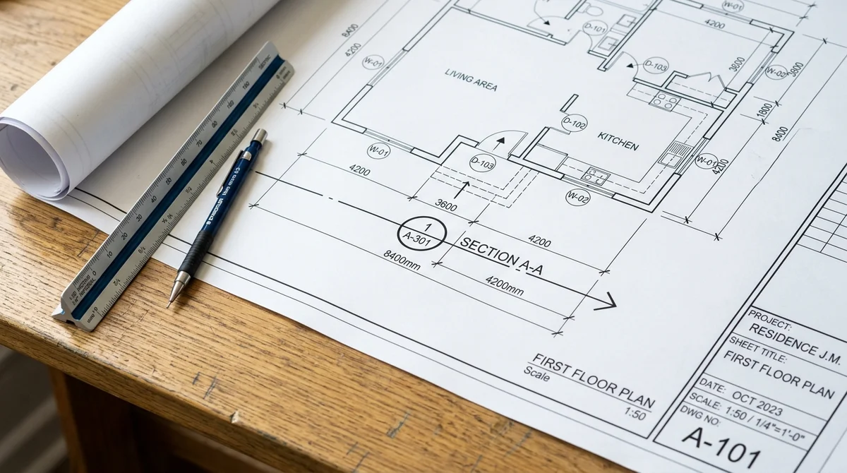
If the scale is missing or inconsistent, do not use that drawing for construction. Municipal reviewers will reject it. For construction, always confirm with your builder which scale and units are being used, and ensure you have the correct scale ruler (imperial or metric) for the drawings provided.
Step 2: Read the Site Plan First
Phase 02The site plan shows the entire lot. It answers zoning questions: - Property lines, easements, and rights-of-way - Setback distances to property lines (measured from wall face) - Existing vs. proposed structures, driveways, and trees - North arrow and drainage direction arrows
Reviewers use this to verify lot coverage, fire separation distances, and compliance with municipal setbacks.
Step 3: Decode Floor Plans & Symbols
Phase 03Floor plans are horizontal slices cut at roughly 1.2 meters above the finished floor. They show: - Wall locations, door swings, and window placements - Room dimensions, clearances, and egress paths - Mechanical/electrical symbols (outlets, switches, HVAC ducts) - Stair geometry and railing requirements
Pro tip: Trace a door swing with your finger. If it hits a wall, fixture, or another door, the drawing has a conflict that must be resolved before framing.
Step 4: Cross-Reference Elevations & Sections
Phase 04Elevations show what the building looks like from each exterior face (North, South, East, West). They confirm siding materials, roof pitch, window heights, and step code insulation thickness callouts.
Sections cut vertically through the building. They reveal what you cannot see on a floor plan: foundation depth, floor-to-ceiling heights, roof framing, and insulation layers. Sections are where builders catch most thermal-bridging and structural conflicts.
Why Professional Drafting Matters
GuideA PDF generated from a stock website rarely includes the cross-references, revision tracking, or BC-specific code callouts that municipal counters require. Properly sequenced drawings reduce RFIs, prevent change orders, and keep your contractor on schedule. If you want to learn how your specific layout translates to permit drawings, our team provides a complimentary drawing review.
Confused by Your Drafts? Get a Free Review
GuideDon't wait until framing starts to discover a clearance conflict or missing code reference. Send us your drawing package for a Complimentary Blueprint Review. We will flag dimension conflicts, missing title blocks, and BC Building Code compliance gaps.
FAQ: Blueprints Decoded
FAQWhat does a revision cloud on a drawing mean?
A revision cloud highlights a specific area that has been updated. Always match the cloud to the revision table in the title block to confirm the change date, description, and approval status.
Can I print construction drawings on standard letter-size paper?
No. Permit drawings are typically 24x36 or 11x17 inches. Printing them on letter paper distorts the scale. Always print at 100% scale or use a calibrated PDF reader to measure dimensions digitally.

Canadian Blueprint Inc.
BC Building Design & Permit Drawings
Published • Updated