Permit Drawing Framework Overview
OverviewSome projects need a compact permit package. Others require a comprehensive drawing set with site planning, 3D modeling, technical detailing, and consultant coordination. Here is the core framework we assemble for municipal review:
building design Set
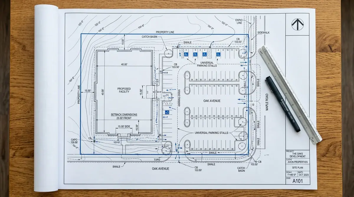
- Site Plans (setbacks, lot coverage & zoning)
- Dimensioned Floor Plans & Space Planning
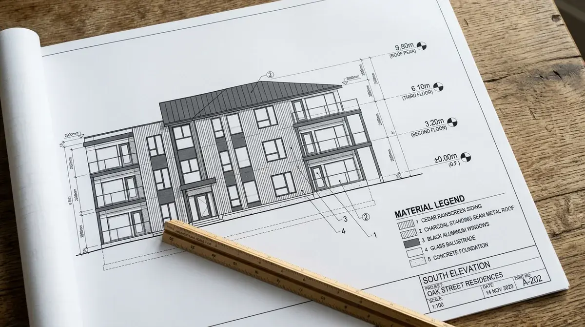
- Exterior Elevations & Building Heights
- Roof Plans & Drainage Outlines
Technical & Code Set
- Building Cross Sections & Wall Assemblies
- Construction, Fire & Energy Code Details
- Reflected Ceiling Plans (RCP) & Lighting
- Means of Egress & Accessibility Layouts
Step 1: Feasibility and Planning Inputs
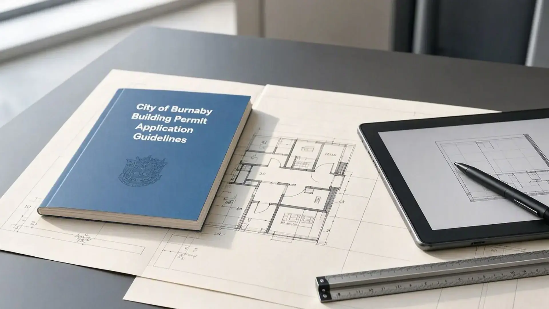
Phase 01Before drawing production ramps up, we define scope using the core planning constraints that drive municipal permit requirements:
- Zoning & Bylaw Analysis: Setbacks, maximum allowable height, Floor Space Ratio (FSR), and lot coverage limits.
- BC Building Code Classification: Establishing Part 9 vs Part 3 thresholds, major occupancies, and spatial separations.
- Site Constraints: Right-of-ways, legal covenants, geotechnical hazards, and environmental setbacks.
Step 2: Existing Conditions
Phase 02Accurate existing-condition drawings prevent on-site construction clashes and municipal plan check delays:
- High-Precision LiDAR Scanning: 3D laser measurement of interior framing, ceilings, and structural points.
- Existing Baseline Drawings: Drafting current floor layouts, foundation baselines, and exterior elevations.
- Demolition Plans: Explicitly identifying load-bearing walls, partitions, and systems to be removed.
Step 3: Site and Preliminary Analysis
Phase 03We analyze the relationship between the proposed structure, legal property lines, and municipal infrastructure:
- Topographic Integration: Aligning BCLS survey coordinates with building 3D surfaces.
- Circulation & Access: Vehicle driveway crossings, accessible pedestrian pathways, and fire department access routes.
- Limiting Distance Calculations: Glazed opening percentages and fire-resistance ratings facing lot lines.
Step 4: Proposed Design Drawings
Phase 04The visible design drawings explain how the project is laid out, how it functions, and how it complies with design guidelines:
- Dimensioned Floor Plans: Room dimensions, door swings, window tags, plumbing fixtures, and accessibility radiuses.
- Exterior Elevations: Front, rear, and side building faces showing cladding materials, rooflines, and spatial calculations.
- Roof Plans: Slopes, valley lines, overhang dimensions, crickets, and rainwater drainage paths.
- Reflected Ceiling Plans (RCP): Lighting layouts, HVAC diffusers, bulkheads, and ceiling heights.
Step 5: Visualization Options
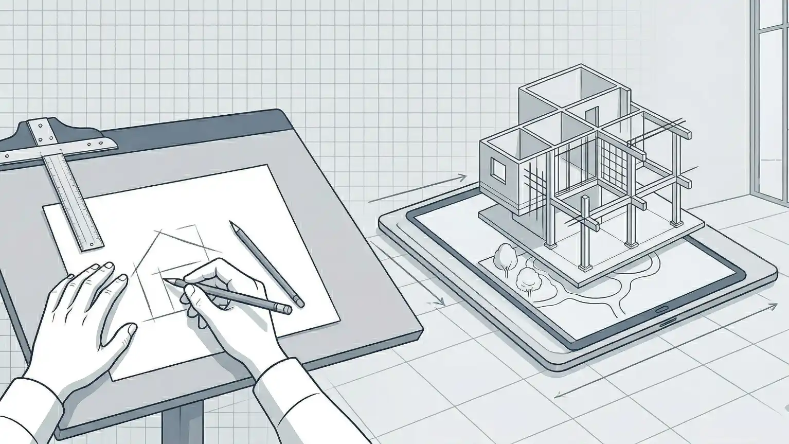
Phase 05Optional 3D modeling and photorealistic visualization clarify spatial relationships before permit submission:
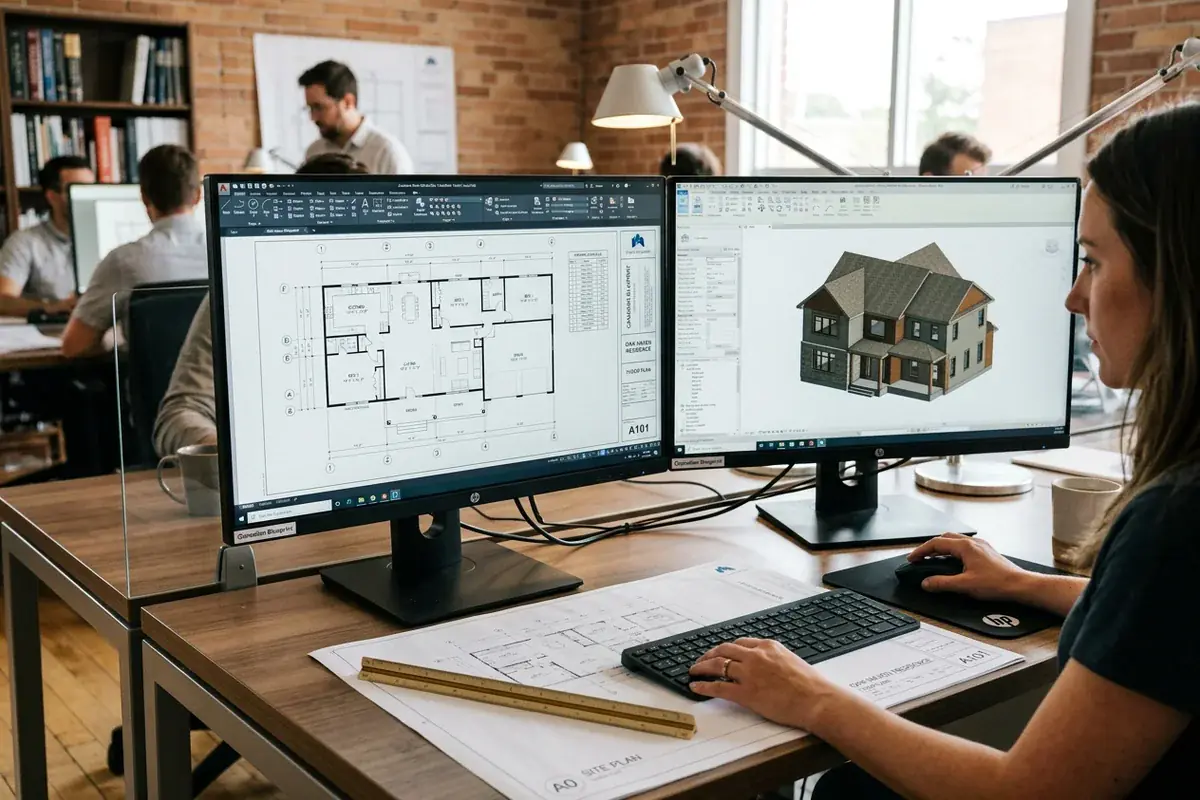
- 3D BIM Models: Navigable 3D building models in Autodesk Revit for multi-discipline coordination.
- Photorealistic Renderings: Exterior and interior perspective renderings for client approvals, investors, or presales.
- Municipal Board Graphics: Context massing views for Advisory Design Panel (ADP) or variance reviews.
Step 6: Technical Permit Drawings
Phase 06The technical detailing package where building officials verify life-safety and energy code compliance:
- Building Cross Sections: Vertical assemblies clarifying floor-to-floor heights, roof trusses, and foundation stepped footings.
- Wall & Envelope Details: Continuous air/vapour barrier details, rainscreen assemblies, and thermal insulation (RSI/R-values).
- Fire & Sound Separations: 1-hour and 2-hour rated demising partitions, resilient channel framing, and firestopping details.
Step 7: Coordination and Revisions
Phase 07Permit success requires active support through the municipal plan check cycle:
- Engineering Coordination: Integrating structural, mechanical, plumbing, and geotechnical engineering drawings.
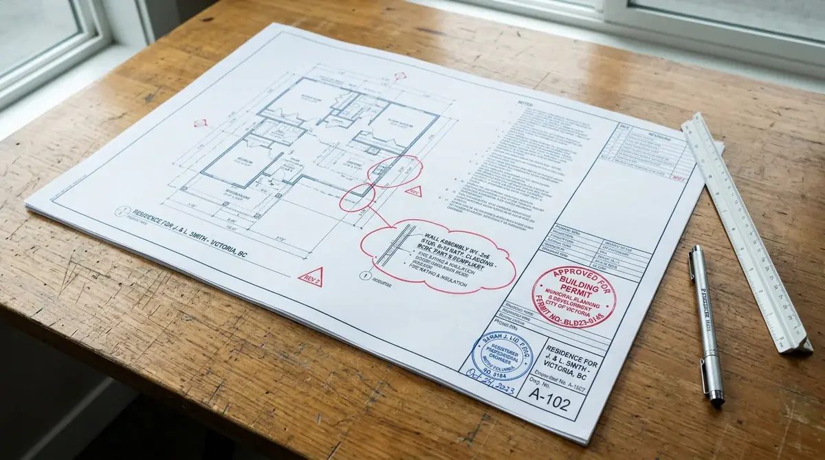
- Plan Check Comment Responses: Rapid turnaround of CAD revisions and written responses to city plan check letters.
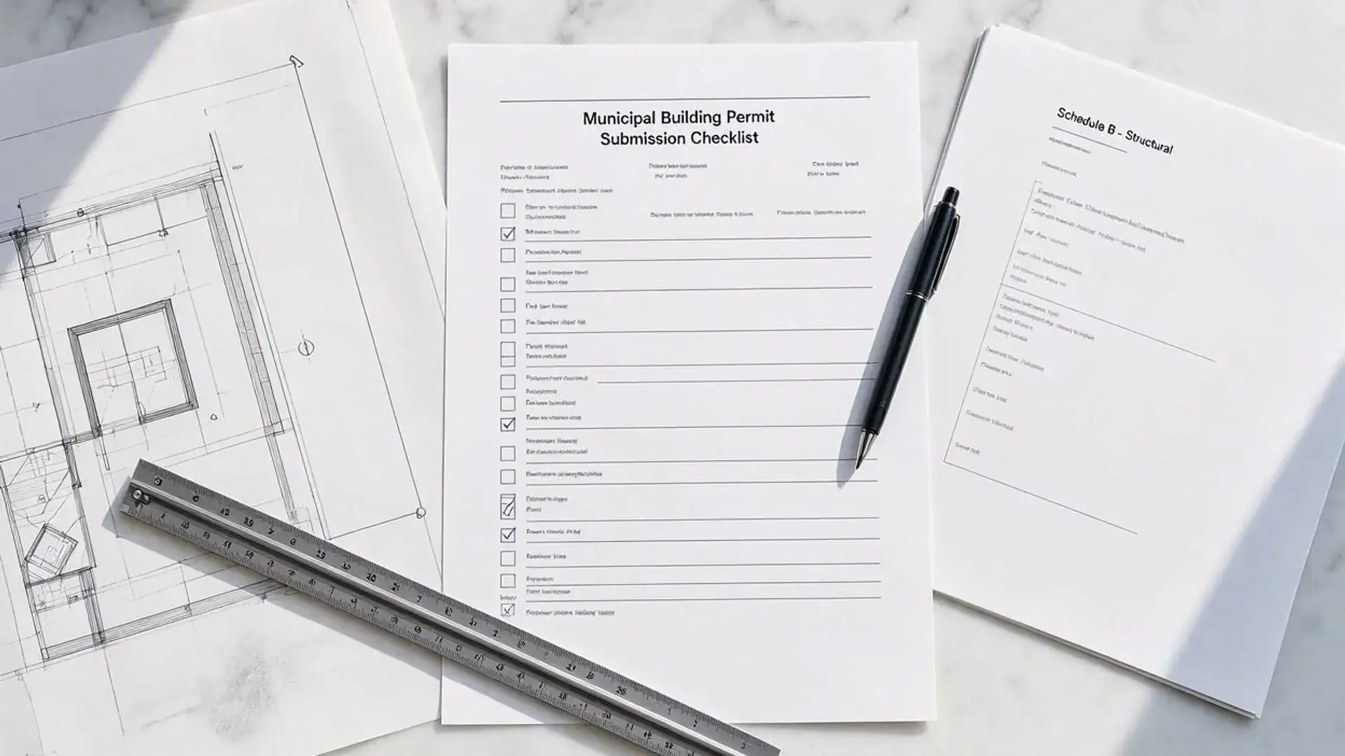
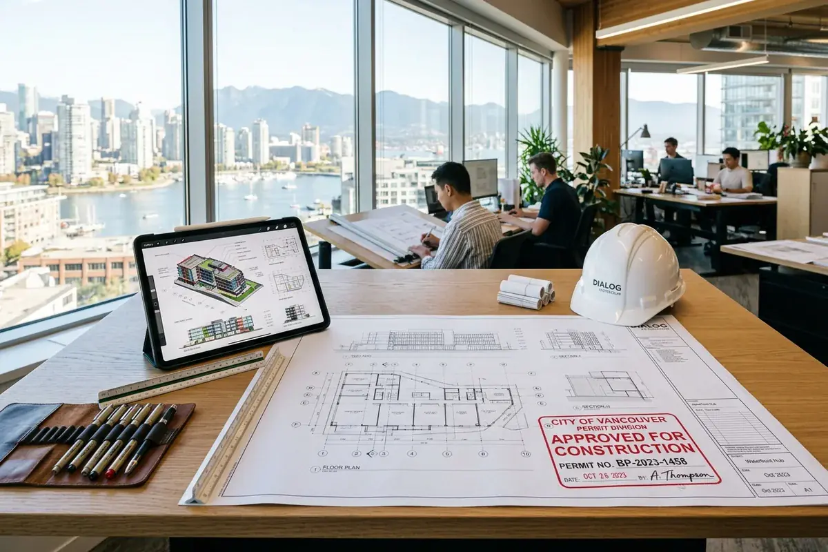
- Final Stamped Package Assembly: Compiling complete, sealed digital PDF sets for official municipal stamping and issuance.

Canadian Blueprint Inc.
BC Building Design & Permit Drawings
Published • Updated